
As not everyone may be familiar with the use of the Direction Switch Mechanism, I would like to start with a (brief) introduction before going into depth on the working mechanism. However, feel free to skip the introduction, if you feel familiar with the topic!
Recently we launched our GBC 42 Linear Loco Lifters. Within this GBC, two arms are used for lifting the GBC balls up into the air, enabling them to gather speed going downhill before entering the Turbo Spin Funnel. See the GBC in action first and take a close attention of the 2 arms that move up and down. It doesn’t matter in which direction you drive the GBC. However the arms automatically go up and down. So how did we accomplish this?
When using the handle or motor, the input/drive axle is only turned in one direction. Usually this would mean, the gears only rotate in one direction aswell, making it turn arms move until they hit an end stop. For the arms to revert the motion and to fulfill their task, a specific system is needed: gears need to be connected and disengaged (turned on and off), changing the direction the axles are rotating. In other words: a Direction Switch Mechanism is needed.
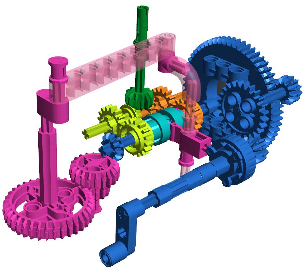
The Direction Switch Mechanism consists out of multiple gears, all with different functions (see image of colored gears). For understanding the mechanism, we have depicted the important gears, using different colors for the different functions. Starting with dark blue, we have got the handle (including the input axle), some gears and an axle leading to the next component. As the input axle rotates, gears are activated, which in turn rotate another axle. On this axle, multiple components (lime green, light blue and orange) are located. As the clutch gears (lime green and orange) have a round centre, they do not rotate directly with the axle. The driving ring (light blue) on the other hand has a ‘+-figured centre’, causing the driving ring to rotate along. When the driving ring is in neutral (the middle) it doesn’t connect with either of the clutch gears, meaning neither of them will rotate. If it moves sideways, it connects with one of the gears, enabling them to rotate another gear which is connected to an axle with a bevel gear (corner gear). This gear then connects with the output mechanism (dark green) which activates the next mechanism (in case of the GBC 42 the arms).
As the mechanism is called the Direction Switch Mechanism, it’s main function is to make something switch direction (no shit, Sherlock…). This switch is mediated by the switch mechanism (pink). The dark blue bevel gear connects with a trio of pink gears, leading to movement of the pink lever (beam on top). On the far side of the lever of the drive ring selector is connected. At the base the drive ring selector connects with the drive ring itself. As the beam on top is moved by the pink gears, the drive ring selector is rotated, clicking the drive ring into the left or right clutch gear. As discussed earlier the drive ring enables the clutch gears to rotate. By alternated pushing the drive ring left and right, the lime green and orange gears are rotated at intervals. Since the clutch gears rotate the output axle in opposite directions, enabling the arms to move up and down! To prevent wear and tear on the system, the two arms balance each other out and they need to cooperate flawlessly: as one goes up, the other needs to go down and vice versa.
While we’re at it, why not immediately combine this motion with a path divider (divides GBC balls over the two lanes) as can be seen in GBC 42? Name it done, simply by connecting another axle with the green output axle (not in image). The possibilities are endless!
The corner stones of the working mechanism being explained, there is one more essential element left: the timing. For the GBC to work, the timing of the arms needs to be perfected: if the direction is switched too early, the balls would not leave the arm, whereas the arms would collide with the next element of the GBC if the switch takes place too late. By using multiple gears of different sizes (small, bigger, big) the timing can be regulated (in this case slowed down) to create just the right momentum! See also the videos below to see the mechanism in action.
Although we zoomed in specifically on the Direction Switch Mechanism in the GBC 42 Linear Loco Lifter, (more or less) similar Direction Switch Mechanisms can be found in different GBCs. Up until now, the mechanism can be found in the following GBCs:
Do you have any questions, feedback or suggestions, please let us know by contacting us!